

Article Summary
A Galvanometer Dual Flight Laser Controller is designed for laser-processing applications that require coordinated scanning and motion-related control. Depending on its architecture and supported interfaces, it may help a system process products moving along a production line while managing galvanometer scan commands and laser timing. This article covers how the technology works, where it is useful, which specifications to evaluate, how to integrate it, and how to troubleshoot common performance problems.
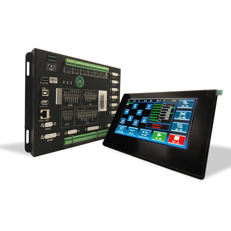
Understanding a Galvanometer Dual Flight Laser Controller
A galvanometer laser system directs a laser beam by using electronically controlled mirrors. These mirrors rotate in response to command signals, steering the beam across a defined working field. Because the mirrors can change direction rapidly, galvanometer scanning is widely used for marking, engraving, coding, and other applications that benefit from fast, programmable beam movement.
A dual-flight laser controller adds a control approach intended for production environments where more than one scanning or processing task may need to be coordinated. The precise meaning of “dual flight” depends on the controller's design. It can refer to a particular arrangement of scanning channels, processing zones, or coordinated flight-marking functions. Buyers should therefore verify the manufacturer's definition, supported operating modes, and hardware configuration rather than assuming that every product using this term offers identical capabilities.
In a typical flying-marking setup, products move on a conveyor or another transport mechanism while the laser marks them without requiring the entire line to stop. The controller must account for product movement so that the marking pattern appears in the intended position and orientation. Where two scanning channels or processing zones are involved, synchronization and workload management become especially important.
Why the Controller Matters
Even a high-quality laser source can produce inconsistent results when its control signals are poorly synchronized with scanner movement or conveyor speed. A suitable controller helps coordinate these operations and provides the command structure needed for repeatable processing. It can also make recipes, marking parameters, and production sequences easier to manage when the system supports those features.
How the Control Process Works
The details vary by model, but a flying laser-marking system generally combines product information, motion information, scanner commands, and laser-control signals. The controller coordinates these inputs according to the configured processing sequence.
Step 1: Receive the Marking Job
The system obtains a marking pattern, text, code, serial number, graphic, or other processing data from its configured software or automation interface. In a production environment, the job may also include a product recipe, positioning parameters, and instructions about when a marking cycle should begin.
Step 2: Determine Product Position and Movement
A sensor, encoder, trigger, or supported external motion interface can provide information about product arrival and conveyor movement. The control system uses the available signals to determine when the product is within the usable processing area and how the marking sequence should be timed.
Step 3: Coordinate Galvanometer Scanning
The controller sends appropriate scan data to the galvanometer system. Scanner calibration, field correction, and the relationship between the marking coordinates and the physical work area all affect the final result. If the product is moving, the control system must compensate for that movement within its supported operating limits.
Step 4: Synchronize Laser Output
Laser activation must correspond to the intended marking path and timing. Depending on the equipment, the controller may use dedicated laser-control signals or an interface compatible with the laser source. Signal polarity, timing, electrical levels, and supported modulation methods must be checked before commissioning.
Step 5: Complete and Verify the Mark
Once the marking cycle finishes, the system can prepare for the next item. A production line may use an external inspection system to verify code readability, mark position, or product identity. Inspection feedback and automatic rejection require suitable hardware and software integration; they should not be assumed to be built into every controller.
Key Benefits for Industrial Laser Processing
1. Reduced Need for Conveyor Stops
In supported flying-marking configurations, the laser can process products while they continue moving through the production area. Avoiding unnecessary stops can improve line continuity and reduce the time spent waiting for a marking station. The achievable benefit depends on conveyor speed, product spacing, marking complexity, and the available scan field.
2. Better Coordination Between Motion and Marking
When product movement is measured and compensated for correctly, marks can remain more consistently positioned relative to the target area. This is especially important for date codes, batch numbers, logos, traceability identifiers, and machine-readable codes placed on moving products.
3. More Efficient Use of Scanning Resources
A dual-channel or dual-zone design may help distribute supported processing tasks or coordinate operations within a production system. However, the actual throughput improvement depends on how the controller allocates work, whether scanning operations can run concurrently, and whether other equipment limits the line speed.
4. More Repeatable Production Recipes
Where software supports stored jobs and parameter management, operators can reuse validated marking settings for recurring products. This can reduce setup variation during product changeovers and make it easier to standardize procedures across shifts.
5. Improved Automation Integration
A controller with suitable trigger inputs, motion interfaces, communication options, and status signals can be incorporated into a broader automation workflow. Depending on the specific configuration, this may simplify coordination with conveyors, programmable logic controllers, sensors, and production management systems.
Production Consistency
Appropriate calibration and synchronized motion control help maintain the relationship between the marking pattern and the moving product.
Operational Efficiency
Validated jobs and predictable control sequences can reduce avoidable setup errors and support smoother product changeovers.
System Coordination
Compatible interfaces make it easier to exchange triggers, encoder information, and process status with surrounding equipment.
Flexible Production
Supported recipes and scanning configurations can help manufacturers handle different product designs without rebuilding the entire line.
Industrial Applications for Dual-Flight Laser Control
The best application for a Galvanometer Dual Flight Laser Controller depends on the controller's supported laser types, scan hardware, processing modes, and motion interfaces. The following examples illustrate common use cases for galvanometer-based laser marking and flying-marking systems.
Packaging and Product Coding
Manufacturers may mark batch numbers, production dates, expiration information, and traceability codes on packaging as it moves along a line. Flying marking can reduce the need to stop each package, provided the product spacing and marking window meet system requirements.
Electronics and Electrical Components
Electronics production often requires compact identifiers, model information, serial numbers, and traceability marks. Consistent positioning is important when available marking areas are small. The selected controller and laser process must suit the substrate, coating, required contrast, and permitted heat input.
Automotive Parts and Industrial Hardware
Metal components may require permanent identification for inventory, quality control, and lifecycle traceability. The marking strategy should account for surface finish, part geometry, reflectivity, and whether the workpiece moves continuously or is indexed into position.
Consumer Goods and General Manufacturing
Plastic housings, labels, tools, and other manufactured goods may need logos, codes, or product information. Since different materials respond differently to laser energy, process trials are necessary to determine suitable parameters and confirm that the mark meets durability and appearance requirements.
Automated Production Lines
Where the line already uses conveyors, encoders, and programmable automation, a compatible flying-marking controller may become part of a coordinated production cell. Before installation, confirm signal compatibility, line speed variation, available installation space, and the response required when a product is missing or incorrectly positioned.
Application suitability should be confirmed with the controller and laser-system supplier. Not every material, laser wavelength, production speed, or dual-flight arrangement is supported by every configuration.
Important Components in a Galvanometer Laser Control System
Understanding the wider system helps buyers identify where a performance problem originates. A controller is one element in a coordinated assembly, and a mismatch between components can limit the results even when each component operates normally on its own.
| Component | Main Function | What to Verify |
|---|---|---|
| Laser controller | Coordinates processing commands, timing, and supported external signals. | Supported modes, software, firmware, interfaces, and dual-flight definition. |
| Galvanometer scanner | Steers the laser beam along the programmed path. | Compatibility, scan speed, field size, calibration, and command interface. |
| Laser source | Supplies the energy used to create the mark or process the material. | Laser type, wavelength, control interface, power range, and modulation requirements. |
| F-theta or focusing optics | Focuses the beam across the working field. | Working distance, usable field, focal spot, and optical compatibility. |
| Encoder or motion feedback | Provides information about conveyor or workpiece movement. | Signal type, resolution, direction, mounting, and scaling. |
| Trigger sensors | Detect product arrival or a process event. | Response time, signal level, placement, and resistance to false triggers. |
| Automation controller | Coordinates the laser station with the wider production line. | Supported I/O, communication protocol, interlocks, and fault handling. |
When evaluating a complete machine, ask the supplier to confirm compatibility across the entire signal chain. A controller that works with one scanner or laser source may require different hardware, configuration, or interface modules to operate with another.
How to Evaluate a Galvanometer Dual Flight Laser Controller
The lowest purchase price does not always deliver the lowest operating cost. A controller that lacks the required interface or cannot handle the intended motion conditions may create expensive engineering work, delayed commissioning, or recurring quality problems. A structured evaluation helps reduce those risks.
1. Define the Actual Production Task
Start with the process rather than a product name. Document the material, marking content, required mark size, target quality, product dimensions, production rate, and whether the workpiece remains in motion during marking. Include current defects and bottlenecks so the proposed solution can address a measurable need.
2. Clarify What “Dual Flight” Means for the Model
Ask the supplier to explain the supported dual-flight configuration in practical terms. Determine whether it involves separate scan heads, multiple processing areas, a particular flying-marking workflow, or another architecture. Confirm which functions can operate simultaneously and which require switching or sequencing.
3. Check Scanner and Laser Compatibility
Confirm the controller's supported galvanometer interface, laser-control signals, and software configuration. Do not assume that matching connector types prove electrical or functional compatibility. Request the relevant interface documentation before committing to the system design.
4. Review Motion Feedback Requirements
Flying marking depends on knowing how the product moves. Verify supported encoder types, signal levels, direction handling, scaling options, and any limits on speed variation. If conveyor speed changes frequently, discuss how the control system handles acceleration, deceleration, and irregular product spacing.
5. Confirm the Usable Working Field
The marking area is influenced by scanner performance, optical configuration, focusing distance, and the required mark quality. A larger field may provide greater positioning flexibility, but it does not automatically provide the same precision or speed at every location. Request representative sample results using the intended setup.
6. Evaluate Software and Operator Workflow
Review job creation, parameter adjustment, recipe storage, user permissions, diagnostics, and integration with existing automation. Clear software workflows can reduce training requirements and lower the risk of operators applying the wrong settings to a product.
7. Ask About Support and Documentation
Confirm the availability of wiring diagrams, configuration instructions, compatible software versions, firmware information, troubleshooting guidance, and technical assistance. For a production-critical line, clarify how faults are diagnosed and how replacement or service requirements are handled.
| Evaluation Area | Question to Ask | Why It Matters |
|---|---|---|
| Processing performance | Can the system meet our actual marking requirements at the target line speed? | Prevents decisions based on headline speed alone. |
| Compatibility | Are our scanner, laser, encoder, and I/O signals supported? | Reduces integration uncertainty and rework. |
| Dual-flight operation | Which tasks or channels can operate concurrently? | Clarifies real throughput and operating limitations. |
| Software | Which job-management and automation features are included? | Helps estimate setup time and operator workload. |
| Technical support | What documents, commissioning guidance, and service support are available? | Helps reduce downtime and simplify maintenance. |
Integration and Commissioning: From Installation to Stable Production
Correct installation is essential for achieving repeatable marking quality. A planned commissioning process helps uncover interface, calibration, and motion problems before the equipment is released for routine production.
Prepare the Mechanical Layout
- Secure the controller, scanner, laser source, and optical assembly according to the equipment documentation.
- Confirm that the laser's working distance and marking field align with the product path.
- Minimize unnecessary vibration and ensure that product guides maintain consistent positioning.
- Provide appropriate ventilation, cable routing, and access for inspection and service.
Verify Electrical and Signal Connections
- Check supply voltage, grounding, cable specifications, and electrical noise considerations.
- Confirm the electrical characteristics of trigger, encoder, laser-control, and status signals.
- Review emergency-stop circuits, protective interlocks, and machine safety functions.
- Follow the controller and laser-source manuals rather than relying on connector appearance alone.
Calibrate and Test in Stages
- Static test: Verify communication, job loading, scanner response, and laser-control behavior using the approved test procedure.
- Position test: Mark a stationary sample and check scale, orientation, distortion, and placement.
- Motion test: Introduce controlled conveyor movement and validate encoder direction, scaling, and trigger timing.
- Production test: Test representative products across the intended speed range and inspect the results.
- Acceptance test: Document approved parameters, sample quality, fault behavior, and recovery procedures.
Troubleshooting Common Dual-Flight Laser Control Problems
When a marking system produces defects, begin by documenting the symptom and identifying when it occurs. Determine whether the problem is constant, limited to a particular conveyor speed, restricted to one scan channel, or associated with a product changeover. This evidence can help distinguish control issues from optical, mechanical, or material-related causes.
| Observed Problem | Possible Causes | Recommended Checks |
|---|---|---|
| Marks shift along the production direction | Incorrect encoder scaling, trigger timing, or motion compensation. | Verify encoder direction and resolution, inspect trigger placement, and repeat a controlled speed test. |
| Distorted characters or graphics | Scanner calibration error, unsuitable correction data, or incorrect coordinate settings. | Check calibration, field configuration, optical setup, and the programmed marking dimensions. |
| Inconsistent marking depth or contrast | Material variation, unstable laser output, focus error, or unsuitable process parameters. | Inspect focus and samples, confirm laser settings, and test a controlled parameter range. |
| Intermittent missed marks | Unreliable triggers, signal interference, incorrect job timing, or product-spacing problems. | Monitor trigger signals, check wiring and grounding, and verify the production sequence. |
| One channel or processing zone fails | Channel-specific configuration, connection, scanner, or job-assignment issue. | Compare channel settings and diagnostic status, then test components using the approved procedure. |
| System stops unexpectedly | Interlock activation, communication loss, power issue, or software fault. | Record the fault state, inspect approved diagnostics, and check the relevant safety and communication circuits. |
Use a Repeatable Diagnostic Sequence
- Record the exact error message, operating mode, product type, and line speed.
- Determine whether the defect occurs in static marking, flying marking, or both.
- Check mechanical positioning and optical focus before changing control parameters.
- Inspect trigger and encoder signals with suitable equipment and approved procedures.
- Review the active job, calibration data, and configuration for the affected channel.
- Change one variable at a time and document whether the result improves.
- Escalate unresolved electrical, firmware, or hardware faults to qualified technical personnel.
Never bypass protective interlocks or safety circuits to keep production running. Laser equipment can present serious eye, skin, fire, and electrical hazards. Troubleshooting must follow the machine manufacturer's safety instructions and applicable workplace procedures.
Maintenance Practices That Help Protect Performance
Preventive maintenance is more effective when it is based on equipment documentation, operating conditions, and recorded performance rather than arbitrary adjustments. A simple maintenance plan helps operators identify changes before they lead to large batches of rejected products.
Keep Optics and the Work Area Clean
Dust, smoke deposits, and other contamination can affect beam delivery and marking consistency. Inspect optical components according to the manufacturer's procedure and use only approved cleaning methods. Avoid touching sensitive optical surfaces or cleaning them with unapproved materials.
Inspect Cables and Connections
Vibration, repeated movement, heat, and poor cable routing can contribute to intermittent faults. Periodically inspect accessible connections, strain relief, grounding, and cable condition according to the maintenance schedule.
Protect Configuration Data
Keep controlled copies of validated jobs, calibration files, and supported configuration settings where the software permits. Record authorized changes to parameters and firmware. A documented backup can shorten recovery time after a replacement or configuration error.
Monitor Quality Trends
Track defects such as shifted marks, unreadable codes, inconsistent contrast, and unexpected interruptions. A gradual rise in defects may indicate a developing issue with focus, material consistency, encoder feedback, or mechanical alignment.
Train Operators on Recovery Procedures
Operators should know how to identify common alarms, verify the selected job, stop the system safely, and report useful diagnostic information. They should not make undocumented changes to scanner calibration or electrical settings without authorization.
Frequently Asked Questions About Galvanometer Dual Flight Laser Controllers
1. What is a Galvanometer Dual Flight Laser Controller?
It is a laser control solution intended for galvanometer-based processing with a dual-flight or related coordinated operating configuration. Its exact functions depend on the specific model, so buyers should confirm supported scan channels, operating modes, motion interfaces, and software capabilities with the manufacturer.
2. What does flying laser marking mean?
Flying laser marking generally means marking a product while it moves along a conveyor or production line. The system uses appropriate motion information and timing to place the marking correctly without necessarily stopping the product for every cycle.
3. Does a dual-flight controller always double production speed?
No. The result depends on the controller's architecture, supported concurrency, marking complexity, scanner performance, laser response, product spacing, and conveyor speed. Ask for application-specific testing instead of assuming that a dual-flight designation guarantees twice the throughput.
4. Which laser sources can work with this type of controller?
Compatibility depends on the particular controller and its supported laser interfaces. Fiber, CO2, UV, and other laser technologies use different process characteristics and may require different control methods. Verify the supported laser types, signal requirements, and configuration before purchasing.
5. Can a controller be installed in an existing production line?
Potentially, provided that the controller is compatible with the existing scanner, laser source, motion feedback, sensors, software, and automation equipment. An integration review should identify any additional interfaces, wiring changes, calibration work, or safety modifications required.
6. Why do marks shift when conveyor speed changes?
Possible causes include incorrect encoder scaling, poor trigger timing, insufficient motion compensation, or speed variation outside the configured operating range. Confirm the feedback signals and test the system at controlled speeds before adjusting the marking parameters.
7. How can I confirm whether a controller meets my production requirements?
Prepare representative samples and define measurable acceptance criteria for marking position, readability, appearance, cycle time, and reliability. Test the proposed configuration using the intended material, marking pattern, optics, and line speed. Request written confirmation of relevant compatibility and operating limits.
8. What information should I provide when requesting a quotation?
Provide the intended application, workpiece material, laser source and scanner model, target marking dimensions, production-line speed, motion-feedback method, required interfaces, marking content, and expected quality. Photos, drawings, sample files, and existing equipment details can help the supplier evaluate the configuration more accurately.
9. Does the controller itself determine the final marking quality?
No. Marking quality is influenced by the controller, scanner, optics, laser source, material, surface condition, focus, calibration, motion stability, and process parameters. A complete-system evaluation is more useful than judging the controller in isolation.
10. What should I check before commissioning the system?
Verify mechanical alignment, electrical compatibility, signal wiring, grounding, safety interlocks, software configuration, scanner calibration, laser settings, and encoder direction. Start with safe static tests, progress to controlled motion tests, and document the final validated parameters.
Build a More Reliable Laser Processing Workflow
A Galvanometer Dual Flight Laser Controller can be an important part of a high-speed laser-processing system, especially when production requires coordinated scanning, motion feedback, and consistent marking on moving products. Its real value comes from how well it matches the application and works with the rest of the equipment.
Before making a purchasing decision, define the process requirements, confirm what the specific dual-flight configuration supports, check compatibility with the laser and scanner, and validate performance using representative production conditions. Careful commissioning, documented settings, and systematic troubleshooting can help manufacturers reduce avoidable downtime and maintain consistent results.
Shenzhen Shenyan CNC Co., Ltd. provides laser-related equipment and solutions for industrial processing applications. To explore a suitable configuration, visit the Shenzhen Shenyan CNC Co., Ltd. official website or review the Galvanometer Dual Flight Laser Controller product page for product-specific information.
Looking for a Suitable Laser Control Solution?
Choosing the right controller starts with understanding your laser source, scanning configuration, production speed, and integration requirements. Share your application details with Shenzhen Shenyan CNC Co., Ltd. to discuss compatibility, technical specifications, and a practical approach to your laser-processing project. Please contact us to learn more and take the next step toward a more efficient and reliable production process.
Explore the Product