

What Are the Key Installation Requirements for Concentric Cable MV in Trench and Duct
2026-06-17
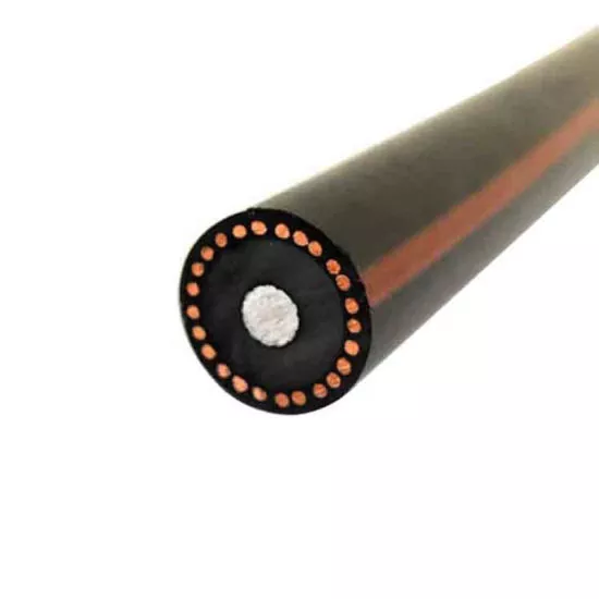
Installing Concentric Cable MV in trench and duct systems demands rigorous planning, precise execution, and strict adherence to safety and performance standards. Unlike single-core or three-core belted cables, the Concentric Cable MV design—with its neutral/earth concentric conductors wrapped around the insulation—offers superior fault current carrying capacity and touch voltage reduction. However, these benefits are only realized when installation practices match the cable’s unique construction. For over a decade, DAYA has supplied Concentric Cable MV solutions to utilities, contractors, and EPC firms worldwide, and we have distilled the critical installation requirements into this practical guide.
1. Pre-Installation Site Survey and Cable Routing
Before any trench is dug or duct drawn, a thorough site survey must identify underground utilities, soil resistivity, water table levels, and potential chemical contaminants. For Concentric Cable MV, the route should minimise sharp bends (minimum bending radius is typically 12× overall diameter for unarmoured designs and 15× for armoured variants). Duct routes must be cleared of debris and sharp edges that could damage the concentric neutral wires. DAYA recommends pulling tension calculations be performed for every duct segment, ensuring the sidewall pressure does not exceed 500 kg/m for XLPE-insulated Concentric Cable MV.
2. Trenching Specifications for Concentric Cable MV
Trench installation is the most common method for direct burial or concrete-encased Concentric Cable MV. Key requirements include:
| Parameter | Requirement | Remarks |
|---|---|---|
| Trench depth (to cable top) | ≥ 0.8 m (roadway) / ≥ 0.6 m (footpath) | Per NEC / IEC 60364 |
| Trench bottom preparation | 100 mm sand or screened backfill, compacted | Free from stones > 10 mm |
| Cable spacing (same circuit) | ≥ 2× overall diameter | For mutual heating reduction |
| Separation from other services | ≥ 300 mm (power) / ≥ 150 mm (comms) | Crossings at 90° preferred |
| Backfill material | Thermal resistivity ≤ 1.2 K·m/W | Use stabilised sand or thermal backfill |
| Warning tape depth | 300 mm above cable | Detectable type required |
For Concentric Cable MV, the concentric neutral wires must not be used as the sole earth electrode; separate earth rods or mats are mandated by most utilities. DAYA always supplies detailed trench drawings with every Concentric Cable MV order to avoid common pitfalls like inadequate compaction or thermal backfill segregation.
3. Duct Installation and Pulling Practices
When installing Concentric Cable MV in ducts (HDPE, PVC, or steel), the following are non-negotiable:
-
Duct diameter: Minimum 1.5× the cable’s overall diameter for straight runs; 2× for sections with bends.
-
Pull rope tension: Use a dynamometer; maximum pulling tension = 50 N/mm² × total conductor area (copper) or 30 N/mm² (aluminium).
-
Lubricants: Only water-based, cable-compatible lubricants – avoid petroleum-based products that attack XLPE or the concentric semicon layers.
-
Bend radius control: Use factory-made or field-fabricated large-radius sweeps (≥ 1.2 m radius for 15 kV Concentric Cable MV).
-
Cable protection: Install nylon or stainless steel pulling socks over the outer sheath, never directly attach to the concentric wires.
DAYA offers pre-lubricated Concentric Cable MV reels and custom pulling heads to reduce installation damage—a leading cause of premature failures.
4. Jointing, Terminating, and Earthing
The concentric neutral of a Concentric Cable MV must be earthed at multiple points (usually both ends and at intermediate joint bays) to minimise touch potentials. Critical installation rules:
-
Sheath voltage limiters (SVLs) : Required for long circuits > 500 m to limit circulating currents.
-
Joint construction: Use heat-shrink or cold-shrink kits rated for the cable’s voltage class; ensure the concentric wires are evenly fanned out and soldered/welded to the earth bar.
-
Termination clearance: Maintain at least 150 mm of exposed conductor for lug crimping—never nick the aluminium or copper strands.
-
Water blocking: Apply swelling tape at all cut ends within 15 minutes of stripping to prevent moisture ingress along the concentric layer.
| Installation Step | Tool / Method | Acceptance Criteria |
|---|---|---|
| Sheath stripping | Rotary stripper | No score marks on insulation |
| Concentric wire fanning | Hand-fanned with spreading tool | Equal gap between wires |
| Crimping | Hydraulic crimper (12–15 tons) | Die colour code matched |
| Torque on earth bolts | Torque wrench | 35–45 N·m (M10) / 50–60 N·m (M12) |
5. Testing After Installation
Every Concentric Cable MV installation must pass:
-
DC hi-pot test (at 4× U₀ for 15 minutes) – but many utilities now prefer VLF (0.1 Hz) AC testing to avoid space charge effects.
-
Sheath integrity test – measure insulation resistance between concentric neutral and earth (> 1 GΩ/km).
-
Partial discharge (PD) measurement – < 10 pC at 1.5 U₀ for new installations.
-
Continuity of concentric wires – each wire’s resistance should be within 2% of the design value.
DAYA provides onsite testing support and calibration certificates for every Concentric Cable MV shipment, ensuring your commissioning team meets grid code requirements.
Frequently Asked Questions (FAQ) – Concentric Cable MV
Q1: Can I install Concentric Cable MV in the same trench as fibre-optic or communication cables?
A1: Yes, but you must maintain a minimum horizontal separation of 300 mm between Concentric Cable MV and telecom ducts, and 600 mm if the MV cable is unarmoured. When crossing, the angle should be 90° to minimise inductive interference. For shared trench scenarios, DAYA recommends using a metallic screen or divided concrete trough for the communication cables. Additionally, the concentric neutral’s earth fault current (up to several kA for 0.5 seconds) can induce voltages in adjacent metallic sheaths—so always bond and earth all metallic enclosures at the same reference point to avoid circulating currents. If separation cannot be met, install a ferromagnetic partition or use armoured Concentric Cable MV (which DAYA supplies on request) to reduce the magnetic field.
Q2: How do I handle water ingress when installing Concentric Cable MV in below-grade ducts that frequently flood?
A2: Water ingress is a primary killer of Concentric Cable MV because moisture migrates along the concentric wire gaps and accelerates water-treeing in XLPE. The essential measures are: (a) use factory-sealed cable ends with heat-shrink caps until pulling; (b) install duct plugs at both manhole ends with inflatable stoppers; (c) apply a continuous water-blocking compound (e.g., swellable powder or tape) over the concentric layer before applying the outer jacket—this is standard in DAYA’s Concentric Cable MV designs; (d) slope ducts towards manholes with drainage sumps; and (e) after pulling, purge the duct with dry nitrogen for 2 minutes to displace humid air, then seal the ends with non-hardening mastic. For permanently wet routes, consider DAYA’s longitudinally water-blocked Concentric Cable MV which incorporates super-absorbent polymer yarns that swell to block water paths within 10 seconds of contact.
Q3: What is the maximum pulling length for Concentric Cable MV in a single duct pull, and how do I reduce tension?
A3: The maximum pulling length depends on tension, sidewall pressure, and jam ratio. For a typical 15 kV Concentric Cable MV (95 mm² copper, 18 mm overall diameter) in a 100 mm HDPE duct with three 90° bends, the safe limit is ~400–500 metres. Beyond that, the pulling tension (using a 5:1 safety factor) exceeds 2,000 kg, risking conductor necking or concentric wire deformation. To extend length: (a) use intermediate pulling pits with rollers and a capstan winch, (b) apply a high-lubricity pulling compound (DAYA recommends our biogenic lubricant that reduces friction by 40%), (c) reduce the number of bends or use larger-radius sweeps, and (d) for pulls > 600 m, use a motorised cable feeder synchronized with the winch to maintain constant speed (≤ 10 m/min). DAYA engineers can run a pull-calc simulation for your specific route and supply intermediate joint kits if the route exceeds 800 m.
Final Checklist Before Energisation
-
All terminations torqued to specified values
-
SVLs installed and polarity-checked
-
Earth resistance < 1 Ω at each gland plate
-
PD levels recorded and below threshold
-
Thermal backfill moisture content verified (≥ 8% but ≤ 20%)
-
Route markers installed at every change of direction
Contact Us for Expert Support on Concentric Cable MV
Installing Concentric Cable MV correctly is not just about following a checklist—it is about understanding the electrical, thermal, and mechanical interactions unique to this cable type. DAYA has helped over 200 projects across 35 countries achieve zero-failure installations, from desert solar farms to coastal wind parks. Whether you need custom reel lengths, pulling calculations, site training, or emergency technical support, our team of MV cable specialists is ready to assist.
Reach out to DAYA today – call our 24/7 helpline, or fill out the contact form on our website. Let us make your Concentric Cable MV project a benchmark of reliability and safety. We respond to all technical inquiries within 4 business hours. Trust DAYA – where every cable comes with a decade of field-proven expertise.