

How Does a Parallel Operation Transformer Improve Power System Reliability?
2026-08-26
Article Summary: A Parallel Operation Transformer configuration allows two or more transformers to work together to supply a common electrical load. When properly engineered, this arrangement can increase available capacity, improve power-system reliability, simplify maintenance planning, and provide a practical path for future load growth. However, parallel operation is not achieved simply by connecting transformers to the same bus. Voltage ratio, vector group, impedance, phase relationship, tap position, protection coordination, and installation quality must all be evaluated before energization. This guide explains the operating principles, selection criteria, load-sharing considerations, installation practices, common problems, and maintenance requirements that help engineers build a stable parallel transformer system.
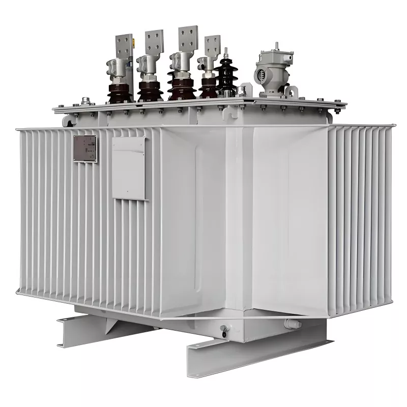
Table of Contents
- 1. Parallel Operation Transformer: An Overview
- 2. How Parallel Transformer Operation Works
- 3. Essential Conditions for Parallel Operation
- 4. Why Vector Group Matching Matters
- 5. How Impedance Influences Load Sharing
- 6. Transformer Capacity and Load Distribution
- 7. Major Benefits of a Parallel Transformer System
- 8. Protection and Control Considerations
- 9. Installation and Commissioning Checklist
- 10. Common Problems and Practical Solutions
- 11. Maintenance and Operational Monitoring
- 12. How to Select the Right Parallel Operation Transformer
- 13. Guangbian Parallel Transformer Solutions
- 14. FAQ
- 15. Conclusion
Article Outline
- Understand the purpose and operating principle of transformer parallel operation.
- Identify the electrical parameters that must be matched before connection.
- Understand how impedance, capacity, and tap settings affect load sharing.
- Recognize protection, commissioning, and maintenance requirements.
- Reduce the risk of circulating current, overload, nuisance tripping, and premature transformer aging.
- Use a structured approach when selecting and specifying a parallel transformer system.
1. Parallel Operation Transformer: An Overview
A Parallel Operation Transformer is part of a power distribution arrangement in which two or more transformers are connected to a common electrical bus and operate simultaneously to supply the same load. Instead of relying on one large transformer, the total required capacity can be distributed among multiple units.
This approach is especially useful when electrical demand changes over time. A factory may initially require moderate capacity but later add production equipment. A data center may need additional transformer capacity as computing infrastructure expands. A commercial facility may also experience substantial differences between peak and off-peak demand.
Parallel operation provides a flexible way to address these situations. However, the transformers must be electrically compatible. Incorrect matching can produce circulating current, unequal loading, overheating, voltage instability, or unnecessary protection trips.
The key principle is simple: transformers connected in parallel must behave as a coordinated electrical system rather than as independent pieces of equipment.
2. How Parallel Transformer Operation Works
Under normal operation, each transformer receives power from the same primary-side system and supplies power to a common secondary bus. The secondary outputs are connected so that their voltages have the correct magnitude, phase relationship, and polarity.
When the system load increases, the transformers collectively provide the required current. Ideally, each unit carries a predictable portion of the total load according to its rated capacity and electrical impedance.
For example, consider two transformers rated at 1000 kVA and 500 kVA. If their relevant operating characteristics are properly matched, a total load of 1200 kVA can theoretically be distributed at approximately a 2:1 ratio:
| Transformer | Rated Capacity | Approximate Load Share | Load at 1200 kVA Total |
|---|---|---|---|
| Unit A | 1000 kVA | 66.7% | 800 kVA |
| Unit B | 500 kVA | 33.3% | 400 kVA |
The actual load division depends on impedance and other electrical characteristics, so engineers should not assume that nameplate capacity alone guarantees proportional sharing.
3. Essential Conditions for Parallel Operation
Before connecting transformers in parallel, several parameters should be checked carefully. These conditions are fundamental to safe and stable operation.
| Parameter | Why It Matters | Potential Problem if Incorrect |
|---|---|---|
| Voltage Ratio | Ensures compatible secondary voltage | Circulating current and voltage imbalance |
| Vector Group | Maintains correct phase displacement | Severe circulating current or connection failure |
| Impedance | Controls current distribution | Unequal loading and overheating |
| Tap Position | Maintains compatible voltage levels | Uneven current sharing |
| Phase Sequence | Ensures correct phase relationship | Fault conditions or abnormal currents |
| Connection Quality | Provides low-resistance current paths | Hot spots and load imbalance |
These parameters should be verified from transformer nameplates, factory test reports, design documents, and commissioning measurements rather than estimated from appearance or model names.
4. Why Vector Group Matching Matters
Vector group is one of the most important considerations when connecting transformers in parallel. It describes the winding connection arrangement and the phase displacement between the high-voltage and low-voltage sides.
Common vector group designations include configurations such as Dyn11 and Yyn0. The designation is not merely a labeling detail. It determines the phase relationship of the transformer output.
If two transformers have incompatible phase displacement, their secondary voltages will not align correctly when connected to the same bus. The resulting voltage difference can drive current between the transformers even when the external load is small.
This current is known as circulating current. It does not contribute useful load power and can create additional heating and losses.
For this reason, the vector group of an existing transformer should always be confirmed before purchasing a second unit intended for parallel operation. A transformer that appears compatible based only on voltage and capacity may still be unsuitable.
5. How Impedance Influences Load Sharing
Transformer impedance has a direct influence on how current is divided between parallel units. When transformers have substantially different impedances, the lower-impedance unit tends to carry a greater portion of the load.
For example, suppose two transformers have similar ratings but their impedances are significantly different:
| Unit | Impedance | Expected Behavior |
|---|---|---|
| Transformer A | 6% | Tends to accept a larger share of current |
| Transformer B | 8% | Tends to accept a smaller share of current |
The result may be an apparently healthy transformer bank in which one unit operates much closer to its thermal limit while another remains lightly loaded. Over time, this can accelerate insulation aging and reduce the practical value of the parallel configuration.
When specifying a Parallel Operation Transformer, impedance should therefore be treated as a design parameter rather than a secondary purchasing detail.
6. Transformer Capacity and Load Distribution
Parallel transformers do not necessarily have to have identical kVA ratings. Different capacities can be used when the electrical characteristics are appropriately coordinated.
However, large differences in ratings can make effective load sharing more difficult. Engineers should evaluate the transformer capacity ratio, impedance relationship, expected load profile, and future expansion requirements together.
- Equal-rated units: Usually provide straightforward load management and redundancy.
- Different-rated units: Can be useful when load growth is gradual or operating conditions vary.
- Multiple smaller units: Can provide greater flexibility during low-load periods.
- One larger and one smaller unit: Requires careful impedance and load-sharing analysis.
For instance, if facility demand varies considerably throughout the day, operators may use one transformer during lighter periods and bring the second unit online when demand rises. This can reduce unnecessary no-load losses compared with operating every available transformer continuously.
7. Major Benefits of a Parallel Transformer System
A properly engineered parallel transformer arrangement can solve several common power-distribution challenges.
Increased Available Capacity
Multiple transformers can provide greater combined capacity than a single unit, allowing the system to support larger electrical loads.
Improved Continuity of Power Supply
If one transformer needs to be removed from service, the remaining unit or units may continue supplying part of the load, depending on system design and available capacity.
Flexible Expansion
Additional transformer capacity can be introduced as a facility grows. This can be more practical than replacing an existing transformer with a substantially larger unit.
Maintenance Flexibility
Parallel configurations can allow individual units to be isolated for inspection or maintenance while other units remain energized, provided the remaining capacity is sufficient and the switching scheme permits it.
Better Response to Variable Loads
Transformers can be staged according to demand. During low-load periods, fewer units may be energized, while additional units can be connected during peak demand.
Reduced Single-Point Dependency
Using several coordinated transformers can reduce reliance on one piece of high-capacity equipment. This can be particularly valuable for facilities where interruption of electrical service has substantial operational consequences.
8. Protection and Control Considerations
Parallel transformer systems require protection schemes that recognize both individual transformer faults and common bus or downstream faults.
Typical protection functions may include:
- Differential protection for internal transformer faults.
- Overcurrent protection for overload and short-circuit conditions.
- Ground-fault protection for abnormal current paths to earth.
- Breaker-failure protection for unsuccessful fault isolation.
- Temperature monitoring for winding and oil thermal conditions where applicable.
- Voltage and current monitoring for abnormal operating conditions.
Protection settings should be coordinated so that the device closest to a fault responds appropriately without unnecessarily disconnecting healthy transformers.
Special attention should also be given to transformer energization. Transformer inrush current can be substantially higher than normal operating current for a short period. Protection settings that ignore this transient behavior may result in nuisance trips.
9. Installation and Commissioning Checklist
Correct equipment selection can still be undermined by poor installation. A disciplined commissioning procedure is therefore essential.
| Stage | Recommended Check |
|---|---|
| Documentation | Confirm ratings, vector groups, impedance, tap range, and test reports. |
| Mechanical Installation | Verify foundation, clearances, grounding, cable routing, and physical condition. |
| Electrical Connections | Check phase sequence, polarity, terminal connections, and conductor sizing. |
| Pre-Energization Testing | Verify insulation, winding resistance, ratio, vector group, and protection circuits as applicable. |
| Load Test | Monitor current distribution and transformer temperatures under load. |
| Handover | Record final protection settings, measurements, and commissioning results. |
Parallel cable runs should also be designed consistently. Differences in conductor length, size, routing, or connection resistance can affect current distribution between transformers.
10. Common Problems and Practical Solutions
Problem 1: Circulating Current
Possible causes: Different voltage ratios, incompatible vector groups, unequal tap positions, or other voltage mismatches.
Solution: Verify transformer ratio, phase relationship, vector group, and tap position before parallel connection. Do not continue operation under abnormal circulating-current conditions without identifying the cause.
Problem 2: Unequal Load Sharing
Possible causes: Impedance differences, cable resistance differences, tap mismatch, or inaccurate current measurement.
Solution: Compare actual secondary currents, transformer impedance data, tap positions, and connection resistance.
Problem 3: One Transformer Runs Hotter
Possible causes: Excessive loading, poor ventilation, unequal load distribution, loose connections, or cooling-system problems.
Solution: Investigate both electrical loading and thermal conditions rather than assuming the problem is caused by ambient temperature alone.
Problem 4: Nuisance Protection Trips
Possible causes: Incorrect protection coordination, unsuitable pickup settings, inrush current, or genuine overload/fault conditions.
Solution: Review relay settings against transformer ratings, system short-circuit calculations, inrush characteristics, and coordination requirements.
Problem 5: Unexpected Voltage Difference
Possible causes: Incorrect tap position, ratio mismatch, or measurement error.
Solution: Compare measured voltage on both transformer secondary terminals under controlled conditions before closing the parallel connection.
11. Maintenance and Operational Monitoring
Once commissioned, a parallel transformer system should be monitored as a coordinated installation. Checking only the total bus load is not enough because one transformer may be carrying a disproportionate share.
Operators should periodically compare:
- Secondary current for each transformer.
- Transformer loading percentage.
- Winding and oil temperatures where applicable.
- Secondary and primary voltage.
- Tap-changer position.
- Protection and alarm records.
- Cooling equipment operation.
- Abnormal noise, vibration, odor, or visible leakage.
- Terminal and cable connection condition.
Trend data is particularly useful. A gradual increase in the current carried by one unit may indicate a developing impedance, connection, tap, measurement, or equipment problem before a serious failure occurs.
Maintenance intervals should be established according to transformer type, operating environment, loading conditions, manufacturer recommendations, applicable standards, and the criticality of the electrical installation.
12. How to Select the Right Parallel Operation Transformer
Selecting a transformer for parallel service requires more than comparing purchase prices or kVA ratings. The new transformer must be compatible with the existing electrical system.
Before requesting quotations, prepare a technical specification containing:
- Rated power in kVA or MVA.
- Primary and secondary voltage.
- Frequency.
- Phase configuration.
- Vector group.
- Percentage impedance.
- Tap-changer type and required range.
- Cooling method.
- Insulation requirements.
- Installation environment.
- Expected load profile.
- Short-circuit requirements.
- Protection and monitoring requirements.
It is also useful to provide the specifications of the transformer that is already operating in the facility. This gives the manufacturer an engineering basis for evaluating compatibility instead of designing the new unit from incomplete information.
When possible, purchasing parallel units from the same manufacturer can simplify engineering coordination, documentation, testing, spare-parts planning, and after-sales support. However, the technical compatibility of the complete system remains the primary consideration.
13. Guangbian Parallel Transformer Solutions
Guangbian provides transformer solutions for customers requiring reliable power distribution and flexible transformer configurations. Its Parallel Operation Transformer offering is intended for applications where multiple transformers need to work together to increase capacity, improve operational flexibility, or support continuity of power supply.
For a parallel transformer project, the most valuable engineering discussion should begin with the customer's existing system rather than with a generic product model. The transformer rating, voltage levels, vector group, impedance, tap requirements, installation conditions, and expected load profile all influence the final configuration.
Guangbian can use these technical requirements as the basis for transformer configuration and project communication. This approach helps customers avoid a common purchasing mistake: selecting a transformer that satisfies the basic voltage and capacity requirements but cannot operate correctly with the equipment already installed.
- Record the existing transformer's nameplate information.
- Confirm its vector group.
- Confirm its percentage impedance.
- Check its voltage ratio and tap position.
- Define the expected total load.
- Determine the required redundancy and future expansion capacity.
- Review protection and switching requirements.
A well-defined specification gives the manufacturer the information required to evaluate the complete operating scenario and reduces the risk of incompatibility during installation.
14. FAQ
Q1: What is a Parallel Operation Transformer?
A Parallel Operation Transformer is a transformer designed or selected to operate together with one or more other transformers connected to a common electrical bus and supplying a shared load.
Q2: Do parallel transformers have to be identical?
No. Transformers with different ratings can operate in parallel when their electrical characteristics are compatible and the system is properly engineered. Voltage ratio, vector group, impedance, phase relationship, and tap settings are particularly important.
Q3: Why is vector group important in transformer parallel operation?
Vector group determines the phase displacement between transformer windings. Incompatible vector groups can produce a significant voltage phase difference and lead to harmful circulating current when the secondary sides are connected together.
Q4: Can transformers with different kVA ratings operate in parallel?
Yes, provided the system has been designed for the combination and the transformers have suitable electrical characteristics. The resulting load distribution should be calculated rather than assumed to be equal.
Q5: What happens when transformer impedance is different?
The transformer with lower impedance generally takes a larger share of the load. Excessive impedance mismatch can therefore cause one transformer to become overloaded while another remains underutilized.
Q6: Can parallel operation improve power reliability?
Yes. Multiple transformers can provide a degree of redundancy. If one unit is removed from service, the remaining units may continue supplying part or all of the load, depending on their available capacity and the system design.
Q7: Is parallel operation suitable for industrial facilities?
It can be highly suitable for factories, manufacturing plants, commercial buildings, substations, data centers, and other facilities with significant or growing electrical demand. The appropriate configuration depends on the facility's load characteristics and reliability requirements.
Q8: What should be checked before energizing parallel transformers?
Engineers should verify transformer ratings, voltage ratios, vector groups, phase sequence, polarity, impedance, tap positions, cable connections, grounding, protection settings, and relevant commissioning test results before closing the parallel connection.
Q9: How can unequal load sharing be identified?
Compare the secondary current and loading percentage of each transformer under the same operating conditions. A persistent and significant difference may indicate impedance mismatch, tap mismatch, connection resistance, measurement problems, or another system issue.
Q10: Why choose a manufacturer with parallel-operation experience?
Parallel transformer projects require compatibility analysis rather than simple equipment replacement. An experienced manufacturer can review existing transformer information, identify critical matching parameters, and help define a configuration suitable for the intended operating conditions.
15. Conclusion
A Parallel Operation Transformer system can be an effective solution when electrical capacity, redundancy, maintenance flexibility, and future expansion are important. By distributing power among multiple transformers, facilities can create a more adaptable electrical infrastructure than may be possible with a single transformer.
However, successful parallel operation depends on engineering compatibility. Voltage ratio, vector group, impedance, tap position, phase sequence, cable connections, protection coordination, and load distribution must all be considered before the transformers are energized together.
The most important lesson is that parallel operation should be treated as a complete system design rather than simply a method of connecting two transformers. Careful specification, testing, commissioning, and monitoring can prevent circulating current, unequal loading, overheating, nuisance trips, and premature equipment deterioration.
For customers planning capacity expansion or looking for a flexible transformer configuration, Guangbian can provide technical support for evaluating parallel transformer requirements and developing a suitable power-transformer solution.
Need a Reliable Parallel Transformer Solution?
Whether you are expanding an industrial power system, upgrading a substation, or planning a redundant transformer arrangement, selecting compatible equipment from the beginning can prevent costly commissioning problems later. Share your transformer ratings, voltage requirements, vector group, impedance, load profile, and application details with Guangbian for a more targeted solution. Contact us today to discuss your Parallel Operation Transformer requirements and find a configuration built around your power system.